RTTY Demodulator Development
Kok Chen, W7AY
w7ay (at) arrl (dot) net
September 1, 2011
This document is an overview of the formative years (1960s)
of RTTY demodulator development.
It is hoped that the document can provide both a historical
perspective for anyone curious about early RTTY
development, and a technical background for anyone wishing
to implement new hardware or software modems. I have
attempted to assemble together the important ideas that
"worked," while also including ideas that were impractical
to implement back in earlier times.
Many of the early circuits end up in the demodulators that
we use today (in algorithmic form in the case of software
modems) and which we take for granted. Some of the older
ideas, a number of which were too complex to implement back
then, became "lost art" and are not present in many of
today's demodulators even though it is now practical to
implement them.
Arguably, two aspects of an RTTY demodulator contribute
most to its performance. One is how well a discriminator
handles different propagation conditions. The second is how
well the RTTY filters provide the best signal-to-noise
ratio to the discriminator while providing the need
interference rejection.
We will discuss these two aspects separately in the
Limiterless
Demodulator page and the
RTTY Filters page.
When it comes to designing high performance demodulators,
dynamic range is always a concern. Because of that, certain
circuits could not be realized in hardware. Today, we have
affordable sound cards with dynamic ranges that exceed 110
dB, and some of the "impractical" ideas in the past may now
be practical. Using floating point arithmetic on today's
fast desktop computers, software modems have practically no
limitations than the ingenuity of their authors. The
dynamic range of an FSK decoder today is largely limited by
the receivers which feed the modems.
The other area where RTTY modems can be improved upon is
the design of the filters. Some of the early RTTY
experimenters eventually realized that optimal decoding of
FSK cannot be done with just any arbitrary narrow band
filters. However, it was not easy to design these optimal
filters back then; using DSP techniques, fewer compromises
have to be made today.
Some of the early demodulators had to compromise on
performance to keep the cost reasonable. We often find
phrases in the old articles such as "not implemented because it
requires 8 additional op-amps." Things that were impractical
in hardware can be implemented with literally just a few
extra lines of software code today.
What got us here?
Radioteletype's roots, and thus the challenges of
demodulating RTTY, can be traced all the way back to
Howard Krum's 1918
patent.
Trained as an electrical engineer, Mr. Krum was the son of
the founder of the Morkrum Company. The elder Krum had
partnered with the head of Morton Salt to form Morkrum.
Morkrum merged with Kleinschmidt in 1925 and changed their
name to Teletype Corporation in 1928.
The challenge back then was to economically transmit
characters from a teletypewriter over a landline. The
teletypewriter's keys were encoded into what we would today
call a 5-bit code.
The principal claim of the U.S. 1,286,351 patent consists
of "initiating the operation
of [a receiver] in response to transmitted impulses at the
beginning of each signal" and "restoring [the receiver]
to a condition of rest at the completion of each
signal."
In modern technical nomenclature, the claim can be
described as "serializing the 5-bit parallel data by adding
a start bit before the data, and adding a stop bit at the
end of the 5 bit data."
Krum's patent permits one to transmit 32 states from a
teletypewriter through a single wire. The start-stop
mechanism synchronizes and maintains the bit order of the
five data bits between the originating teletypewriter and
the receiving teletypewriter.
This patent gave us the way to eventually transmit a
radioteletype
signal by modulating a transmitter between just two states.
We take the operations of UARTs and serial ports for granted
today. Back in the beginning of the 20th century, the
start-stop method had to be invented. The '351 patent
was filed in 1910 and issued in 1918. Today, we would
call it a "killer app."
(Technology has come full circle –
many of the
advanced digital modulation modes will transmit 16, 64 or
even more states with a single modulation symbol. Modern
codes such as Varicode used in PSK31 are also "self
clocking," and no longer use start-stop bits for
synchronization.)
Selective Fading
Very early radioteletype (RTTY) had used on-off keying
(OOK) of a carrier (as done for Morse transmissions) to
encode the two states (on and off) that Howard Krum's
system generated. After dealing with the various problems
of OOK, amateurs quickly moved to sending one state with a
carrier at one frequency, and the second state as a carrier
at a different frequency (in other words, Frequency Shift
Keying or FSK). One of the two FSK frequecies is called the
Mark frequency and the other is called the Space frequency.
However, FSK has its own set of problems. One of which is
caused by selective fading.
Selective fading causes unequal signal strengths in the
Mark and Space channels. Selective fading in a Rayleigh
channel can cause two carriers to randomly and
independently fade to different depths. A panoramic view of
a HF spectrum often shows a notch that pans across a wide
band signal.
FSK demodulators started out being of the
limiter-discriminator variety. The audio FSK signal from a
receiver is first passed through a limiter to remove any
amplitude variation. The limited signal then passes through
two resonators that are tuned to each of the two FSK tones.
In his June 1963 article in the RTTY
bulletin, Frank Gaudé K6IBE shows
graphically what happens when a signal with equal Mark
and Space durations but with different amplitudes is
passed through a limiter; the demodulator output
shows unequal
durations!
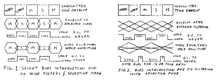
On the left (Figure 1 in Mr.
Gaudé's article), an FSK signal with a Mark tone that is 24
dB stronger than the Space tone is first limited and then
detected. Figure 2 shows an FSK signal with the same amount
of selective fading that first is put through a comb
filter.
The comb filter consists of two narrow bandpass filters
that are centered around the Mark and the Space tones to
reject interference elsewhere. Today, the more popular name
for the "comb filter" is a "dual peak filter."
Figure 1 shows unequal (25 ms/19 ms) output durations even
though the input has equal Mark and Space durations. After
passing through a dual peak filter, the output discrepancy
is even worse, becoming 37 ms and 7 ms.
Gaude's article pretty much drove modem designers to
implement "AM" detectors.
Optimal Filtering
In a 1964 article "Filters For
RTTY," Victor Poor K3NIO (of
Frederick Electronics Corp.) wrote:
"No other factor in the design of RTTY equipment bears as
much on performance as the filters used to separate the
received signal from the surrounding noise.
At the same
time, however, there is probably less understood [sic] by
the average amateur about the design of filters than any
other aspects of RTTY." [emphasis is mine - kc]
Mr. Poor goes on to explain that an optimal data filter
needs to satisfy the slicing and sampling points that he
showed in the following figure:
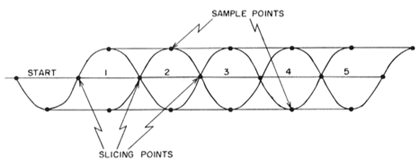
The slicing and sampling points
are defined by the "Nyquist Criterion" to avoid
Inter-symbol Interference (ISI) between adjacent data bits.
(H. Nyquist, "Certain Topics In Telegraph Transmission
Theory," AIEE Transactions, Vol 47, April 1928 pp 617-644.)
This topic is discussed in more detail in a following
section on Filters.