Selective fading causes the amplitude of the Mark tone to vary randomly relative to the amplitude of the Space tone. In the early days of amateur RTTY, FSK was exclusively detected by first passing the signal through a limiter before it reaches the Mark/Space discriminator circuit. Today, we often call this FSK limiter-discriminator technique an "FM" demodulator.
The limiter was expected to handle not just flat fading where both Mark and Space channels fade in unison, but it was also expected to handle selective fading.
The ATC — Frank Gaudé K6IBE's Pioneering work on Limiterless Two-Tone Demodulators
As mentioned in the previous section, Frank Gaudé K6IBE wrote a seminal article in the June 1963 issue of the RTTY bulletin entitled "A New Approach to TU Design Using a Limiterless Two-Tone Method" that changed the understanding of limiters and selective fading. It subsequently opened up rapid acceptance among amateurs of the limiterless method for demodulating FSK.
Limiterless demodulation is what we often today call the "AM" method for demodulating FSK.
Mr. Gaudé explained how selective fading causes timing errors at the output from a discriminator when the signal is passed through a limiter. The performance degrades further when the RTTY signal is first filtered by what we today call "dual peak filters."
In subsequent articles in the RTTY bulletin, the term "limiterless two-tone demodulator" was sometimes shorten to just "two-tone demodulator."
Allnatt, Jones and H. B. Law's Paper
To support his point, Gaudé referred to the paper by Allnatt, Jones and Law in the March 1957 Proceedings of the (British) Institute of Electrical Engineers which provided both theoretical and measured results showing fewer decoding errors from a limiterless detector than from a detector that uses a limiter. A block diagram from the Allnatt paper is reproduced below (the block diagram included a two-receiver diversity system):
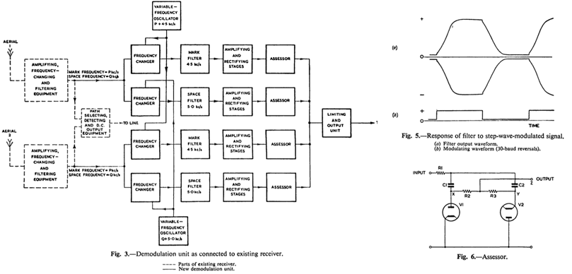
An interesting thing to note is
that Allnatt et al had attached an "assessor" circuit
to each
individual Mark and
Space channels. The assessor circuit itself appeared as
Fig. 6 in the Allnatt paper (shown at the bottom right in
the composite figure above).
Subsequent amateur implementations of the Automatic
Threshold Correction (ATC) have adopted a more economical
scheme that works on a composite (Mark minus Space) signal.
Correcting the threshold of a composite signal first
appeared as the subject of a patent (U.S. Patent
2,443,434). The 1948 "Automatic
Signal Bias Control Means and Apparatus" patent was
invented by Robert Sprague of the Press Wireless, Inc..
Sprague's automatic thresholding circuit was also
granted a Canadian Patent CA 465,405 in 1950.
The ATC/assessor corrects any Mark and Space amplitude
imbalance before the slicer thresholds the receive signal
into the discrete output Mark and Space states. The Press
Wireless patent's primary aim was to find the correct black
and white levels from an FM-based FAX receiver.
Note that the Allnatt block diagram shows the use of mixers
("frequency converter") to create fixed intermediate
frequencies, where the demodulation ("rectifying") and
adaptive thresholding ("assessor") take place.
An intermediate frequency system is often used in more
expensive HF modems to allow the Mark and Space tones to be
varied (shown as the Mark and Space "Variable Frequency
Oscillators" in the block diagram above). Some software
modems today use a "direct conversion" scheme to move the
tones around, with the intermediate frequency stages
consisting of in-phase (I) and quadrature (Q) baseband
signals (i.e., a DC based intermediate frequency).
Notice that one of the intermediate frequencies in the
Allnatt paper is centered at 4.5 kHz, while the other is
centered at 5 kHz. This was done so they could initially
test their system without using the mixers, by applying an
FSK signal with a 4.5 kHz Mark tone and 5.0 kHz Space tone.
The paper mentioned that to simplify the implementation,
they had linearly summed the assessor output even though a
square-law weighting should have been used. (The square-law
refers to Leonard Kahn's "Ratio Squarer" for diversity
systems.) When the same scheme is done in software today,
the compromise to not include a square-law correction no
longer needs to be made.
The graph that is reproduced below shows one of the results
in the Allnatt paper:
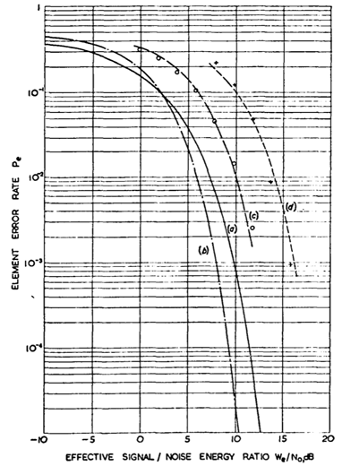
Although a little hard to read,
you can see the measured AWGN performance from what they
called "conventional receiver" (i.e., limiter based)
plotted as crosses near the theoretical "(d)" curve. The
measured performance of their limiterless receiver are
plotted as circles near the "(c)" curve. Notice that there
is about 4 dB of SNR (horizontal scale) improvement.
To put it in perspective, this performance gain is about
the equivalent of the directivity improvement when
switching from a dipole antenna to an optimal two element
Yagi-Uda beam. The plots in the Allnatt paper for a
"two-path fading signal" shows even larger performance
gains.
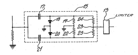
The figure below is taken from the Press Wireless patent.
It shows the patented circuit (shown as item 15) that is
almost identical to the circuit to the "assessor" of
Allnatt's paper (but preceding the paper by almost 10
years).
The ideal equations that govern
the above circuit appear in the Frequency Shift Keying
section of the Data Transmissions chapter of
Marvin Frerking's text
.
Something to note is that the Frerking's ATC models more
closely the Allnatt paper (the use of separate assessors
for Mark and Space channels) than the more economical
composite ATC circuit that was presented in the Press
Wireless patent and used in amateur circles back then. The
methods are different under severe multipath case. With
software implementation, there is less reason today to
avoid the Allnatt (and Frerking) approach.
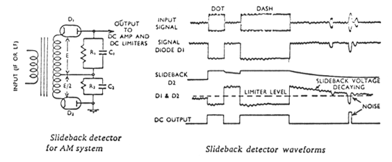
The
Gaudé/Harris Slideback Detector
The following shows the circuit
of one half of the mark/space "slideback detector" pair
that was presented in Gaudé's article. Gaudé had attributed
the circuit also to Bruce Harris W5HCS.
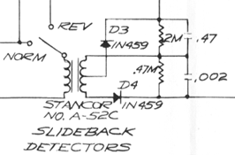
The Norm/Rev switch reverses
the Mark/Space circuits to copy inverted signals. D4,
together with the 2000 pF capacitor and 470 kΩ resistor,
appears to form a standard AM detector. D3, together with
the 0.47 µF capacitor and 200 kΩ is a detector with a
longer time constant are used to track the fading envelope
of the Mark or Space signal.
The Gaudé/Harris circuit thus encompasses both the AM
detector and the ATC. The "accessor" used by Allnatt et al,
and the circuit in the '434 Press Wireless patent are what
we would today call post-processors to perform only the ATC
function. The 0.47 µF capacitor in the Gaudé/Harris circuit
performs the same function as the capacitor that is
labelled "21" in the Press Wireless Patent.
Beard
and Wheeldon paper and Danes and Tibble paper
Jim Haynes WA9IBB (now W6JVE)
reviewed two papers that are related to limiterless
demodulation in the August 1963 issue of the RTTY bulletin.
One paper was written in June 1960 by J. V. Beard and A. J.
Wheeldon in the Point-to-Point Telecommunications magazine.
[Point-to-Point
Telecommunications was a publication of the
Marconi Company. Unfortunately, I can no longer find a copy
of the Beard and Wheeldon paper – kc ] [Edited August 2012: Mr.
Haynes has since forwarded a copy of this paper and also
the Danes and Tibble paper mentioned below to me. David
G3YYD had also forwarded a scanned copy of the Beard and
Wheeldon paper to me — many thanks to both
gentlemen.]
Beard and Wheeldon pointed out the importance of correctly
copying the start bit. They showed that start bit errors
that are caused by poor thresholding of the FSK signal,
possibly an FSK signal from a slow typist, more than
triples the error rate when a start bit is misidentified.
(This should no longer be a problem with the application of
diddles, as alluded to more recently here.) As reported in Jim
Haynes' review, the authors continued by stating that a
two tone demodulator is "superior in HF
operation where selective fading is
encountered." [the quote is directly from
the Haynes article – kc]
Again, the Beard and Wheeldon paper had preceded amateur
use of the FSK AM detector by a couple of years.
A second paper that was reviewed by Jim Haynes appeared in
the November 1962 issue of Electronic Engineering, written
by J. E. Danes and D. V. Tibble, with the tiltle "A
Flexible System for Receiving FSK Signals."
The authors of this second paper also noted
"the
superiority of two tone detection over other methods when
selective fading is present." [also a direct quote from the
Haynes article – kc]. Haynes had commented that the "ratio
corrector" that is used by the two authors was very similar
to the Gaudé slideback detector.
Haynes said in his review of the Danes and Tibble paper:
(Those who work with Matched Filters can probably relate to this statement in connection with 45.45 baud systems that use 170 Hz shifts.)
Interestingly, Mr. Haynes said the following:
When Haynes wrote that, amateurs have not yet stumbled upon the 1961 Page Communications DTC patent. It had to wait until Victor Poor's 1964 article.
Robert Weitbrecht W6NRM's Two-Tone Demodulator
Gaudé's article was followed by Robert Weitbrecht W6NRM's "What Is This Two-Tone Detector?" article in the September 1963 issue of RTTY bulletin. Mr. Weitbrecht had modified existing terminal units (his Mark II and Mark IV TU) to incorporate the limiterless demodulator and reported on the performance improvement.
Mr. Weitbrecht wrote,
He then pointed out something that was not, up to that point, obvious in amateur circles,
By treating the Mark and Space tones as different signals that appear at separate locations in the spectrum, you end up with an FSK demodulator that benefits from frequency diversity properties. Having earlier (1960) experimented with diversity reception using two receivers, Weitbrecht recognized the frequency diversity properties from the limiterless demodulator which a limiter-discriminator demodulator does not provide.
With a good ATC circuit, one also need not worry about the amount of RTTY shift. Before 1956, amateurs in the USA were only allowed to use a nominal shift of 850 Hz (with an allowance of 800 Hz to 900 Hz). This rule was amended by the FCC in February of that year which allowed amateurs to use any shift that is "less than 900 cycles." Because of the selective fade problem with FM demodulators, many had welcomed the permission to use a narrower 170 Hz shift.
AM demodulators removed any disadvantage of using a wide shift.
In a February 1964 article in the RTTY bulletin, Frank Gaudé reported that there is actually no significant difference anyway between the amount of selective fading between a wide shift and a narrow shift signal down to the 170 Hz region.
Weitbrecht included a figure that was taken from the paper by Beard and Wheeldon, which shows the earlier slideback circuit, illustrating the slow decay of the slideback voltage:
Weitbrecht's implementation of the demodulator (showing
both the mark and space slideback detectors) looks like:
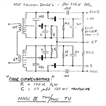
Note that the time constant of
his "fade compensators" worked out to be 170 ms, the period
of a 60 wpm (45.45 baud) RTTY character.
In some circles, in particular demodulators from Dovetron,
the slideback detector/fade compensator/ATC circuit is also
called an axis
restorer.
The DTC — Victor Poor K3NIO's Contributions to Limiterless
Demodulators
In his
January 1964 article in the RTTY bulletin ("A Second Look
At Limiterless FM Detection") Victor Poor, K3NIO
pointed out
three drawbacks with the limiterless demodulator and how
they are actually related.
The limiterless demodulator works poorly when there is high
impulsive noise and when the signal is rapidly
fading. The third
and more serious problem for amateurs is that the ATC works
poorly with a slow typist.
During a pause in keying, the ATC circuit sees only a Mark
signal and mistakenly assumes that the Space signal has
selectively faded. Victor Poor steered the amateur
community for the first time to the Page Communications DTC
patent and explained how the DTC
fixes the problem of the ATC. One of the circuits from
the patent is shown here:
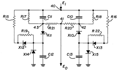
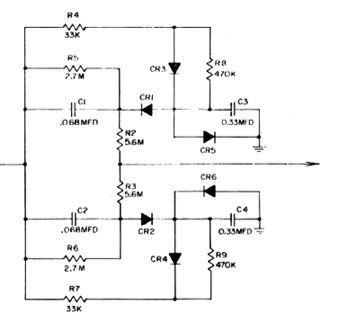
Mr. Poor's proposed circuit
follows closely the Page Communications patent:
The DTC is probably no longer
critical in the era of diddles today. However, the DTC
could still be useful for the impulse noise problem, but it
should be pointed out that the DTC will fail when copying
Mark-only or Space-only signals.
ATC/DTC in the Mainline Demodulators
By
the time Irv Hoff, K8DKC
published his
Mainline TT/L Demodulator in the November 1964 issue of
the RTTY bulletin, the DTC circuit has become a standard
feature of the demodulator.
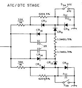
Mr. Hoff had included a switch
to short out the "DTC capacitor" to make his circuit
function like a plain ATC.
In December 1964, Mr. Hoff coauthored "Current RTTY
Receiving Techniques" in the RTTY bulletin with Keith
Petersen, W8SDZ. The article included an overview of the
known ATC and DTC techniques up to that point in time. In
the article, the authors went as far as to compare the
impact of the DTC to RTTY with that of the atomic bomb!
In the article, they had also pointed out that the only
real disadvantage of the DTC is for Mark-only and
Space-only copy (which the switch in the above figure is
used for).
Epilog
In the
short time span between June 1963, when Frank Gaudé
published the first limiterless demodulator article, and
December 1964, when Irv Hoff and Keith Petersen wrote the
"Current RTTY Receiving Techniques" article, the AM
demodulator had become the established RTTY demodulator in
amateur circles, and it remains so today.
In between those dates, Robert Weitbrecht had pointed out
the Frequency Diversity properties of the AM demodulator
and Victor Poor had introduced the amateur world to the
Page Wireless DTC circuit.
The short time span is undoubtedly due to of the fact that
by 1963, the commercial world already had both the ATC and
DTC methods patented, and the scientific world had already
done studies to show the superiority of limiterless
demodulation.
The most influential patent is arguably the Page
Communications DTC patent, which Victor Poor, K3NIO took
full advantage of to design his DTC circuit, and the most
important scientific paper is probably the one by Allnatt,
Jones and Law, which heavily influenced Frank Gaudé,
K6IBE's slideback detector.
Some circuits that were used in the early days are only
approximations of the objectives of ATC and DTC operations.
Today, with software implementations, we can implement ATC
and DTC algorithms which are much closer to the design
objectives. Furthermore, with today's processor speeds, the
complexity of the ATC or DTC is no longer is an
impediment.