It is known that a Matched Filter is optimal under additive white Gaussian noise (AWGN) conditions. A matched filter is one whose impulse response is the time inverted version of waveform of the actual signal that is to be decoded. In the case of 45.45 baud RTTY, the match filter's impulse response is therefore a rectangular function that is 22 milliseconds long.
The bandwidth of a matched filter is very wide. The envelope of the transfer function in the frequency domain falls only at the rate 1/f, which is not surprising since the envelope of the keying sidebands of a single RTTY bit falls as 1/f. To counter interference, something narrower is desired.
Frank Gaudé K6IBE suggested in his September 1963 RTTY bulletin article "Two-Tone, Shifts And Filters," that a narrow linear phase filter with a bandwidth of 60 Hz tends to work well.
It is however left to Victor Poor K3NIO to present the real definitive requirements (the Nyquist Criterion) for any filter to perform optimally for filtering RTTY data so that individual data bits do not interfere with one another (so called "inter-symbol interference" or ISI).
As touched on earlier, Mr. Poor gave two necessary conditions that an optimal data filter must meet. The two conditions govern location of the "sample" and "slicing" points of the filtered data waveform, as shown in the figure below:
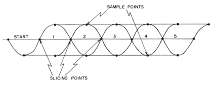
For the filter to work
optimally, the points where a waveform are sampled need to
all have an identical constant amplitude, regardless of
whether the data stream consists of alternating bits (such
as a Baudot RYRY sequence) or if there are two or more
consecutive Mark or Space bits.
The second necessary condition is that the output waveform
from the filter has to pass though zero at locations which
are halfway in between the sample points.
Mr. Poor went on to show exemplary filters whose eye
patterns satisfy the condition for the sampling point.
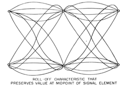
Notice that all waveforms in
the above figure pass thorough the same sample points (the
six small open circles that are just visible in the
diagram). However, the waveforms differ in between the
sampling points, therefore they cannot all meet the second
condition which he gave.
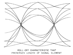
The following is his example of waveforms from filters that
meet the slicing point condition (the two small circles),
but again, naturally they cannot all meet the sample point
condition:
Finally, Poor shows waveforms
from three exemplary filters that satisfy both of his
conditions:
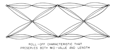
Mr. Poor calls the above "eye
pictures." "Eye patterns" is a more common name for
these diagrams today.
As emphatically stated by Mr. Poor, the proper filter has
nothing to do with being "wide enough to let the third (or
fifth or umpteenth) harmonic pass." For any design
bandwidth, the optimal filter has to meet his two
conditions.
The matched filter is optimal when the noise is Gaussian
and has constant power at all frequencies. When noise power
is not constant, or if there is an interfering signal
nearby, a filter with narrower passband is more optimal,
but the filter still has to meet the two conditions laid
out by Mr. Poor.
Restating Victor Poor's main point in modern filter
nomenclature, the two conditions are satisfied if
(1) to preserve the mid-bit sample points, the frequency
response shape must be a brick wall filter plus a shape with odd
symmetry (and an additional even symmetry in the
imaginary component) about the frequency that is equal
to one-half the bit rate,
and
(2) to preserve the slicing points, the frequency response
must be cosine function from DC to the frequency that is
equal to one half the bit rate, plus a shape with even
symmetry (and an additional shape with odd symmetry in the
imaginary component), about the frequency that is equal to
one-half the bit rate.
In Nyquist's 1928 paper
the two
conditions above are presented as Figure 2 (condition 1)
and Figure 3 (condition 2):
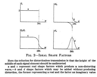
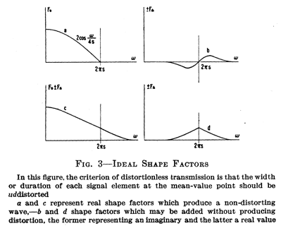
Victor Poor had only mentioned
the real parts of the filter (the top figures in Figure 2
and bottom figures in Figure 3 in Nyquist's paper) because
he was working with inductors and capacitors on a real
signal. Today, with software modems, we can use in-phase
and quadrature (I and Q) signals and we have greater
liberty to exploit Harry Nyquist's original model. Of the
imaginary components, Nyquist stated, "Each one of [the
imaginary shape factor] may of course be combined with any
one of [the real shape factor]."
There are an infinite number of filters that meet condition
(1) but not condition (2), and similarly, there are also an
infinite number of filters that meet condition (2) but not
condition (1). We need a filter that meets
both
conditions.
For a 45.45 baud RTTY signal, the filter that has the
narrowest bandwidth and still meets the above two
conditions is the Raised-cosine Filter
whose cutoff is
22.7 Hz. A raised-cosine filter is a Nyquist filter, i.e., it has a response of
zero at sampling points other than its own sampling
point, thus satisfying Victor Poor's sample point
criterion.
A general
raised-cosine
filter is actually not a single filter, but a family of
filters with a roll-off parameter β which takes a value
between 0 and 1.
The raised-cosine filter with β of 0 has the sharpest
roll-off and is the same as a rectangular brick-wall
transfer function that passes no signal beyond 22.7 Hz on
either side of the center frequency. It will be virtually
impossible to properly tune a signal through such a
transfer function, and a pulse will also ring for an
infinite time.
The raised-cosine filter with β of 1 has the widest
roll-off and its transfer function is a cosine function
between -π and +π that is raised by a DC term that is equal
to the amplitude of the cosine (the properties which give
the filter its name). In the case of 45.45 baud RTTY, the β
= 1 raised-cosine filter has a non-zero response that
extends up to 45.45 Hz on either side of the center
frequency. It also has the shortest ringing in the time
domain of all the raised-cosine family and appears to be
the "raised-cosine" that Victor Poor chose to use.
Notice that the optimal raised-cosine filter (irrespective
of the β) will pass only the fundamental of the keying
sideband.
When there is no nearby interference, widening the filter
bandwidth by using other forms of the Nyquist filter that
pass more keying sidebands can improve the signal to noise
ratio. This is because an RTTY signal is itself quite wide.
In the extreme case, when there is no bandwidth limitation,
the filter that has the best SNR is a Matched Filter (which
by the nature of its definition, is a Nyqust filter).
An AWGN matched filter is one which connects the sample
points in the eye pattern with straight lines. (i.e., the
eye pattern looks like triangular waves). Victor Poor
understood this since he says this about a matched filter:
"Maximum signal-to-noise ratio in the case of RTTY does not
come with minimum bandwidth. Maximum signal-to-noise ratio
comes with what is called a "matched filter."
Mr. Poor goes on to discuss good approximations to the
optimal Raised-cosine filter. For practical reasons, he
suggests using a third order Butterworth approximation. With today's
software modems, it is easy to get a much better
approximation to the Raised-cosine function than a third
order Butterworth function.
Single
Tuned Filters
In their "Current RTTY Receiving Techniques" article in the
December 1964 issue of the RTTY bulletin, Irv Hoff and
Keith Petersen published the following plot made by Tom
Lamb K8ERV, showing filters that are constructed with 88 mH
toroids at different Q and comparing them to an ideal
Raised Cosine transfer function and Victor Poor's 3rd order
Butterworth approximation:
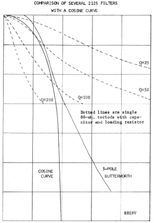
Notice that with a Q of about
50, a single tuned circuit provides a good match to the
raised cosine, down to about -10 dB. However, it flares out
faster than both the ideal filter and Victor Poor's 3rd
order Butterworth, thus it will pass through more noise and
be more susceptible to interference. With a Q of 25, a
single tuned circuit will let through too much noise and
interference, and with a Q of 100, a single tuned circuit
will be too narrow to properly pass single bit transitions
(e.g., an RYRY pattern) from a weak signal.
Epilog
When using a modem that already
includes an optimal filter, you should not use a filter in
the receiver that is too narrow since doing so will cause
the combined receiver filter and modem filter to no longer
meet the Nyquist conditions that are laid down by Victor
Poor's article.
With a software demodulator that includes a matched filter
or a raised cosine filter that matches the baud rate of the
RTTY signal, the receiver's filter
should be only as narrow as needed to keep interference
from clipping the sound card.
Please remember this each time
you are tempted to use a narrow crystal filter. If you are
still not convinced, read Victor Poor's article.