cocoaModem Synchronous AM Receiver
Kok Chen,
W7AY [w7ay
(at) arrl (dot) net]
Last updated: November 16, 2009
Index (User's Manual - Synchronous AM Receiver)
General Information
Aural Monitor
Accessibility (Incremental Speak and Voice Assist)
Macros
RTTY Interfaces
PSK Interface
MFSK Interface
Hellschreiber Interface
CW Interface
ASCII Interface
SITOR-B Receiver
HF-FAX Receiver
Synchronous AM Receiver
Versions
Part II
Synchronous AM Receiver
Selective Fading can cause the carrier of an Amplitude Modulated (AM) signal to be attenuated relative to the AM signal's sidebands, to the point where the signal appears over-modulated and thus sound severely distorted when envelope detected.
One way to overcome this weakness is to filter out the AM carrier, and then using a product detector for demodulation (i.e., receive the AM signal as an DSB-SC signal). The remaining problem is the need to precisely tune the receiver.
Often, one of the AM sidebands is also filtered away -- this results in lowered signal-to-noise ratio but has the advantage of not requiring precise phase locking and it also provides the ability to choose a different sideband when there is adjacent interference from one side -- usually a bigger problem with shortwave broadcast stations than signal to noise ratio.
Synchronous demodulation is usually performed in the intermediate frequency stages of a receiver (e.g., the Sony ICF-2010) and involves extracting the AM carrier to phase lock a local oscillator to. That phase locked local oscillator is then used by the product detector. The phase locked loop automatically fine tunes the product detector.
Rather than using signals from the intermediate frequency stages of a receiver, cocoaModem achieves synchronous AM by applying DSP techniques to an SSB receiver's output that is slightly off-tuned to the AM signal. It involves no hardware modification to the receiver.
Demodulation Scheme
Figure 1 shows the scheme used in cocoaModem's Synchronous AM demodulator.

Figure 1 -
cocoaModem Synchronous AM demodulator
The input is a regular (real) signal from an SSB receiver
that is off tuned by approximately 200 Hz so that you can
actually hear a 200 Hz tone caused by the AM signal's
carrier.
For carrier extraction, the input signal is lowpassed to
remove the modulation sidebands and then mixed with a
quadrature mixer -- two mixers with a quadrature local
oscillator feeding them, where the local oscillator's
frequency tracks the tone of the carrier. The phase locking
is performed by taking the derivatives (see reference) of the in-phase (I) and
quadrature (Q) outputs of the mixers and then computing
the offset to be applied to the local oscillator to
bring it to the same frequency as the "carrier."
The extraction of sideband information is similar to the
Weaver method (also called the "third
method" of SSB modulation and demodulation) except that
one of the local oscillators has an extra 200 Hz offset
which is locked to the carrier.
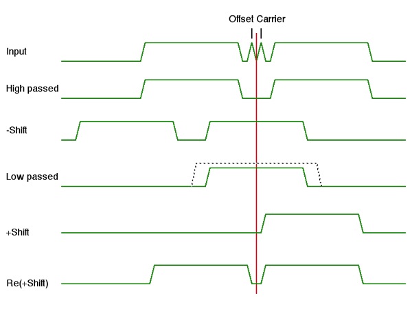
Figure 2 shows the spectra as the signal goes through the
demodulator.

Figure 2 -
cocoaModem Synchronous AM spectra
As shown in Figure 2, the real
signal is first passed through a high pass filter to remove
the offset carrier. The remaining signal is not yet usable
since the original input came from a signal that was tuned
200 Hz too high. To move both sidebands towards DC by 200
Hz, one of the sidebands is first removed. This is hard to
do in the analog domain (as witnessed by the lack of good
analog implementation of SSB transmitters using the Weaver
method) but easy to achieve in the DSP domain
The high passed signal without the carrier is first shifted
down in the spectrum by mixing with a quadrature local
oscillator (f- in Figure 1) set to a frequency of about 2
kHz. The aim here is to center one of the sidebands around
DC and then apply a low pass filter to remove the other,
unwanted sideband. This is shown as the -Shift
signal in Figure 2.
Identical low pass filters are applied to the down shifted
signal to extract just one of the sidebands from this
analytic signal (also called a
complex or a quadrature signal). By maintaining a
quadrature pair to represent the signal, the spectrum of
a signal need not be symmetrical about DC (the red
vertical axis in Figure 2).
After being lowpassed, the remaining sideband is now
shifted back up on the spectrum (+Shift signal in
Figure 2), but this time by a local oscillator (f+ in
Figure 1) that is tuned about 200 Hz lower in frequency
than the down shift (f-) oscillator. As shown in Figure 1,
the precise amount of offset (nominally 200 Hz) is
controlled by the same offset value that controls the
carrier loop. The carrier loop only exists for the sake of
deriving this offset number. (The upshift local oscillator
could also have be implemented by mixing the downshift
local oscillator with the oscillator that is locked to the
carrier, but in the digital domain, it is just as easy to
create a numerically controlled downshift oscillator).
The real (spectrum symmetric around DC) signal is then
formed from the +Shift signal and passed to the
output audio device.
Synchronous AM
Interface
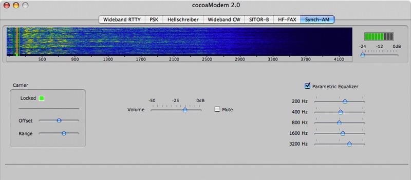
Figure 3 shows the Synchronous AM interface in the
cocoaModem window.

Figure 3 -
cocoaModem Synchronous AM Interface
At the top of the window, you will see the familiar
waterfall display, with the input signal level and input
attenuator on its right. The spectogram starts a few
scanlines from the bottom of the waterfall display to
accommodate the green carrier phase locked loop marker.
There are two vertical range markers. This is the range the
AM signal's carrier should fall in for carrier lock to take
place. The center of the range is nominally at 200 Hz, but
it can be adjusted using the Carrier Offset slider
that is below the waterfall.
To tune a station properly, use either your receiver's
upper sideband suppressed carrier (USB) or lower sideband
(LSB) mode. If you select USB, tune your receiver 200 Hz
lower than zero beat, and if you are using LSB,
tune your receiver 200 Hz higher than zero beat.
In either case, you should hear a moderately loud 200 Hz
tone from the receiver's speakers. Turn down the receiver's
speakers so it does not interfere with the audio from the
synchronous demodulator.
The carrier will appear as a strong vertical line in the
spectogram, near the 200 Hz offset in the waterfall label.
Fine tune the receiver/transceiver so that the carrier is
in between the two green range markers of the waterfall.
Adjust the Offset and Range sliders if you need to, to
center the carrier as much as possible in between the green
marker lines.
In case your receiver does not allow sufficiently fine
tuning to bring the AM carrier into the lock range, the
offset slider allows you to chose a carrier offset between
100 Hz and 300 Hz. Try not to use a carrier offset that is
too low since you might get interference from 50/60 Hz hum
if you have sufficiently bad ground loop problems between
your receiver and your computer. Except for the carrier
tone, the region in the spectogram in between the green
range markers should appear moderately clean.
The range slider can be widened to allow easier tuning.
However, with weak stations or stations that transmit a lot
of low frequency content, you may want to narrow the lock
range as much as possible to improve the ability of the
oscillator to remain in lock.
There is a bold green marker below the spectogram and in
between the thin green range marker lines. This indicates
the frequency of the carrier extraction local oscillator.
If the carrier is between the range lines, you should see
the bold green bar move towards the carrier in the
spectogram. The Locked indicator that is below the
waterfall should turn yellow when you are close (within 2
Hz) to lock and the indicator turns green when you are
phase locked to the carrier.
It might take a second or two for lock to take place. If
the Locked indicator flashes yellow occasionally,
you may want to reduce the lock range -- adjust the
Range and Offset sliders to reduce any
interference.
Because cocoaModem's synchronous demodulator uses only one
of the sidebands of the AM signal, precise phase lock is
not too crucial and the audio could be usable even when the
Locked indicator is yellow.
What you should notice in the Aural channel is that there
is much less distortion caused by selective fading. The
volume of the signal can still swing up and down (it
depends on the AGC of the receiver) but the volume
variations should no longer be accompanied by severely
distorted audio.
In addition to the level control in the Aural Config, there
is a convenient volume control in the main window and there
is also a mute checkbox.
There is an audio Parametric Equalizer that you can use to
fashion the audio spectral profile to your liking or to
compensate for headphones/speakers characteristics. You can
disable the equalizer with its checkbox and it is an
effective way to check if your equalizer settings in an
improvement over the non-equalized sound. The equalizer is
implemented in an FIR filter by using a small inverse FFT
on the slider settings, and following the inverse FFT with
a DSP window. The FIR filter's kernel is recomputed each
time you move one of the parametric equalizer's slider.
If there is interference from an adjacent station, you
might be able to get cleaner reception by choosing a
different sideband to demodulate the AM signal. Switch the
receiver between USB and LSB reception and retune for lock.
Configuration
Configuring the Synchronous AM interface is simple. Open
the configuration window from the Window menu in
cocoaModem's Main Menu. Select the input device from the
Receiver config. The output from the Synchronous AM
interface goes to cocoaModem's common Aural Monitor. The maximum
output volume is fixed from the slider in the Aural
monitor. The volume control in the Synch-AM interface
allows further adjustment from that maximum value.
Back (Introduction)