Kok Chen, W7AY
October 23, 2014 (updated: October 29, 2014)
Introduction
By satisfying the Nyquist conditions, relatives of the Raised Cosine Filter are often used as a data filter because the raised cosine waveform avoids inter-symbol interference (ISI).
A baseband signal that is generated by passing impulses through a Raised Cosine Filter that is designed for the symbol period generates no inter-symbol interference when the output is sampled at the center of the symbols.
A common use of the raised cosine function (for example, with GMSK that is used in GSM mobile phones) applies identical Root Raised Cosine filters at both the transmitter and the receiver so that the cascade of the two filters combines into a Raised Cosine transfer function. Instead of using rectangular pulses, the root raised cosine filtered waveforms from the transmitter also helps limit the emitted keying sidebands.
Some of the legacy modulation standards use rectangular pulse amplitude modulation as their baseband symbols. The FSK implementation of amateur Radioteletype (RTTY) and amateur Morse transmissions (CW) are among emissions that use rectangular shaped symbols. Even though these transmissions are often filtered or waveshaped to reduce keying sidebands, the baseband waveform remains predominantly rectangular in shape.
The optimal (in the SNR sense) linear filter that satisfies the Nyquist conditions for rectangular pulses are Matched Filters whose impulse response are also rectangular pulses.
The Raised Cosine filter satisfies the Nyquist condition only when the input are impulses; it does not satisfy the Nyquist condition when the input are finite duration rectangular RTTY pulses. Even though some inter-symbol interference exists when the Raised Cosine filter is used to filter rectangular pulses, it is often still preferred to the Matched Filter due to the latter's susceptibility to interference from an adjacent signal.
The family of "extended" Raised Cosine strikes a compromise between the wider bandwidth of an ISI-free Matched Filter and the amount of ISI from a Raise Cosine filter. For pulse transmissions, each order of the extended raised cosine filter has successively lower ISI until it converges to a Matched Filter.
In this article, we investigate the use of frequency equalization on the Raised Cosine to account for the rectangular pulses, and the use for RTTY demodulation.
The Raised Cosine Filter
The transfer function of a Raised Cosine is given as:
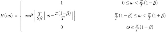
where β is the excess bandwidth of the Raised Cosine.
The following figure shows the response of the filter to a sequence of impulses with a narrowest pulse separation of T,
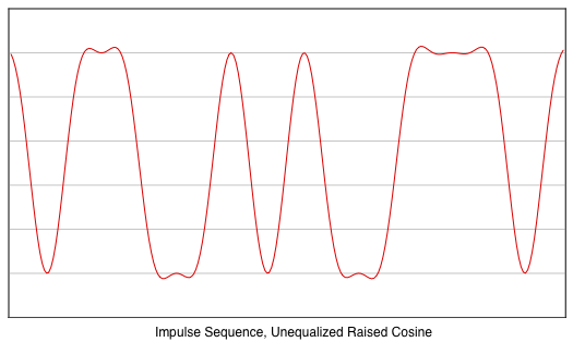
As expected, the impulses that
represent the data symbols have no affect on one another's
output, illustrating the primary Nyquist condition.
The following figure shows the response of the same filter
for the same data sequence when the impulses are replaced
by
pulses that have a duration of T (what
you will typically see from one of the tones of an RTTY
signal),
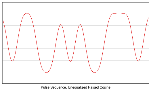
Notice that there is a
significant amount of inter-symbol interference: alternate
bits of 1 and 0 smears into one another. A symbol "0" that
is in between two "1" symbols does not fall all the way to
the baseline. Similarly, a symbol "1" that is in between
two "0" symbols does not rise to the maximum peak. There is
about -8 dB of ISI.
If automatic threshold correction (ATC) is not used, an
RTTY signal with just 8 dB of selective fading (or a 8 dB
FSK carrier imbalance) will cause unusable amounts of
decoding errors even under good SNR conditions. The errors
are not coming from the noise, but from ISI when there is
imbalance of the FSK tones.
A lower ISI for the pulse sequence can be achieved by using
a Raised Cosine filter with a wider bandwidth:
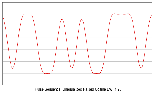
The above shows the response of
a Raised Cosine filter with a bandwidth that is 25% wider
than the optimal bandwidth for impulses. While the ISI is
reduced to less than -20 dB (and improves RTTY selective
fading performance when SNR is good), the filter also has 1
dB wider noise bandwidth, which degrades bit error rate
when SNR is poor even in the absence of selective fading.
The
Extended Raised Cosine Filter
The infinite order
Extended Raised Cosine
filter is
equivalent to a Matched Filter and therefore has no ISI
when used with pulse signals. However, like the Raised
Cosine filter, a low order Extended Raised Cosine filter
also produces ISI when used with pulse signals.
The Extended Raised Cosine filter has significantly less
ISI than the regular Raised Cosine filter. The following
shows the output from a 2nd order Extended Raised Cosine
(the 1st order "Extended Raised Cosine filter" is basically
a regular Raised Cosine filter.).
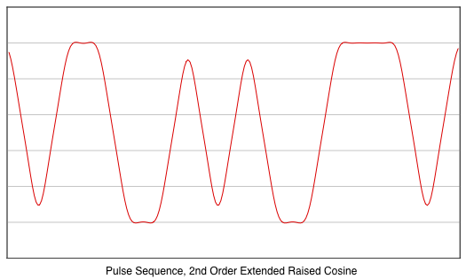
Notice that this extended
raised cosine filter already has an ISI (-20 dB) that is
similar to the 25%-widened raised cosine filter bandwidth
(previous figure).
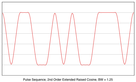
When the bandwidth of the 2nd order Extended Raised Cosine
is also made 25% wider, as seen below, it has practically
no ISI from a pulse signal. Even for low orders, the
Extended Raised Cosine filter clearly has an advantage over
the simple Raised Cosine filter.
Equalized Raised Cosine
Amplitude equalizing the raised cosine for rectangular
pulses is discussed by K. Feher [Feher1], and the Hewlett-Packard
book [Feher2] and white papers which Feher had influenced.
When a rectangular pulse is filtered by a Raised Cosine
Filter, by the Convolution Theorem, the resultant spectrum is
the spectrum of the pulse multiplied by the transfer
function of the filter.
To achieve no ISI, the transfer function of a filter that
is optimized for pulses therefore needs to be the transfer
function of the Raised Cosine divided by the Fourier
transform of a rectangular pulse.
Given a pulse of width T, the amplitude of the Fourier
transform of the pulse is,
![]()
the transfer
function of the equalized Raised Cosine is therefore
defined (adapted from p.14 of [Feher2] and p.49 of
[Feher1]) as,
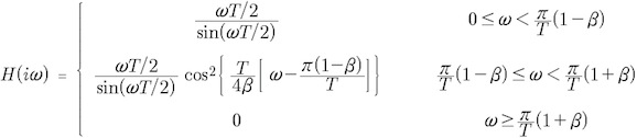
Notice that this transfer function reaches zero (the third
condition in the equation above) at exactly the same
frequency (![]() ) as the standard Raised
Cosine transfer function. The interference rejection
capability of the equalized Raised Cosine and the
regular Raised Cosine are therefore similar.
) as the standard Raised
Cosine transfer function. The interference rejection
capability of the equalized Raised Cosine and the
regular Raised Cosine are therefore similar.
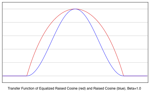
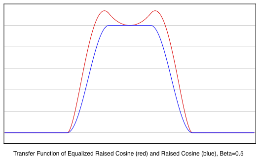
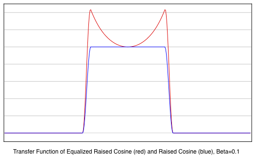
This is shown in the following three plots that compare the
transfer functions H(jω) of the Equalized Raised Cosine
(red curves) with the unequalized Raised Cosine (blue
curves) for three different excess bandwidth (β) values.
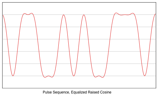
The
pulse driven
response of the Equalized Raised Cosine (β=1) is shown
below. This plot is identical to the response of the
impulse driven,
unequalized Raised Cosine filter that is
shown earlier. With the added equalization term, there is
no need to widen the bandwidth of the filter to achieve
zero inter-symbol interference for pulse sequences.
Impulse Response of the Raised Cosine Filters
Although the transfer function
of the Raised Cosine is described with piecewise segments,
a single closed-form expression of the impulse response of
a Raised Cosine is well known (see here for example). For β=0, the
impulse response is further reduced and simplified to
the sin(x)/x function.
The impulse response of the Extended Raised Cosine is
expressed as a recursion on the simple Raised Cosine
impulse function. By flattening the recurrences, a
closed-form expression for the impulse response of the
finite-ordered Extended Raised Cosine therefore also
exists.
There is however, no closed-form expression for the Raised
Cosine that is equalized for pulses. This is not a problem
when the filter is implemented by performing the
convolution with forward and inverse FFT (i.e., by directly
apply the Convolution Theorem, also called the
Overlap-and-add algorithm) since only the
transfer function of the filter is needed. When
performing filtering using direct convolution (i.e., by
using a dot product), the impulse response will need to
be obtained.
If the symbol period T is large compared to the sampling
period, the impulse response of the pulse-equalized Raised
Cosine can be obtain by simply applying the inverse FFT to
a sampled version of the transfer function. This is shown
in Appendix A. The sampled impulse
response will need to be recomputed each time either the
symbol rate or
sampling rate
changes.
Conclusion
What
we have shown is that a regular Raised Cosine filter has
strong (-8 dB) inter-symbol interference ISI when it is
used to filter pulsed signals. This is especially important
when demodulating an RTTY signal that has undergone
selective fading since the ISI induced errors will be
created even when noise is not present.
With such a large ISI, a reliable automatic threshold correction
(ATC) has to be
used to counter selective fading conditions.
Unfortunately, ATC has its own error mechanisms (for
example, not perfectly tracking the fading period), and
it is preferable to use a filter that has less ISI, so
that a "weak" ATC algorithm can be used instead.
We have also shown that a regular Raised Cosine filter with
25% wider passband has a moderately usable (-20 dB) ISI
when used to filter a pulsed transmission, and in the case
of RTTY, it fails only when the selective fading is deeper
than 20 dB.
A filter with wider bandwidth can withstand more selective
fading, but it also passes through more noise. By changing
the bandwidth of the Raised Cosine filter for lower ISI, we
are basically trading off good selective fading performance
with good high-SNR performance.
Although the ISI is still non-zero with pulse signals, the
Extended Raised Cosine filter has less ISI than the regular
Raised Cosine filter.
Finally, the pulse equalized Raised Cosine filter has no
ISI whatsoever. With this filter, there is almost
unneccessary to use automatic threshold correction to
counter selective fading.
References
[Nyquist1] H. Nyquist, "Certain Topics
In Telegraph Transmission Theory," AIEE Transactions,
Vol 47, April 1928, pp. 617-644.
[Feher1] K. Feher, "Digital
Communications: Microwave Applications," Prentice-Hall,
Englewood Cliffs, N.J, 1981.
[Feher2] K. Feher ed.,
"Telecommunications Measurements, Analysis, and
Instrumentation," Prentice-Hall, Englewood Cliffs, N.J,
1987, pp. 13-14.
Appendix
A: Code Sample that returns the Impulse Response of an
Equalized Raised Cosine
The
following code segment returns an Equalized Raised Cosine
for a given sampling rate (in samples/second) and symbol
rate (in baud). beta
is the Raised
Cosine excess bandwidth (between 0 and 1).
The result is an impulse response with N floating point
samples, with symmetry around the sample N/2.
#define kFFTSize 4096
void equalizedRaisedCosineImpulse( float *result, int N, float beta, float samplingRate, float baud )
{
complex H[kFFTSize], h[kFFTSize] ;
float dF, T, u, v, f, f1, f2, cosine ;
int i ;
dF = samplingRate/kFFTSize ; // frequency scale
T = 1.0/baud ; // symbol period
// note: 6 dB passband f = 0.5/T
f1 = ( 1-beta )*0.5/T ;
f2 = ( 1+beta )*0.5/T ;
H[0] = 1 ; // DC term
H[kFFTSize/2] = 0 ; // Fs term
// positive frequencies
for ( i = 1; i < kFFTSize/2; i++ ) {
f = i*dF ;
if ( f <= f2 ) {
u = kPi*f*T ;
v = u/sin( u ) ; // preemphasis
if ( f <= f1 ) H[i] = v ;
else {
cosine = cos( kPi/(4*beta)*( 2*f*T - (1-beta) ) ) ;
H[i] = v*cosine*cosine ;
}
}
else H[i] = 0 ;
}
// negative frequencies
for ( i = 1; i < kFFTSize/2; i++ ) H[kFFTSize-i] = H[i] ;
// for the symmetrical spectrum, the inverse FFT should return vector with zero imaginary components.
iFFT( H, h ) ;
result[N/2] = crealf( h[0] ) ;
for ( i = 1; i < N/2; i++ ) result[N/2+i] = result[N/2-i] = crealf( h[i] ) ;
// normalize
v = 0 ;
for ( i = 0; i < N; i++ ) v += result[i] ;
for ( i = 0; i < N; i++ ) result[i] /= v ;
}
The function iFFT (implementation not shown) performs a complex 4096 point inverse FFT that takes 4096 complex input array H, and writes the inverse transform into the complex array h, also with 4096 samples.
The following is the impulse response (red curve) that is computed by the routine above for a sampling rate of 3000, symbol rate 45.45 baud, beta = 1 and N = 396.
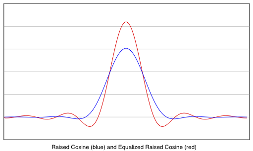
For comparison, the blue curve
is the impulse response of a regular (unequalized) Raised
Cosine with β=1.
Notice that the zero crossings of the two impulse responses
do not
coincide. The
Equalized Raised Cosine also rings for a longer time.