Kok Chen, W7AY
February 23, 2012
Expanded: March 7, 2013
Introduction
In a 1928 paper, H. Nyquist described the necessary and sufficient conditions for a filter to pass a telegraph element without being subjected to intersymbol interference.
For a rectangular signaling pulse shape, the Nyquist filter which has the narrowest bandwidth is a Raised Cosine filter. However, in the absence of adjacent channel interference, the wider Matched Filter outperforms the Raised Cosine filter under Additive White Gaussian Noise (AWGN) conditions.
This paper describes an effective method for deriving other filters which obey the Nyquist criteria. For a rectangular pulse, these extended Nyquist filters have bandwidths that are in between the bandwidth of the Raised Cosine filter and the bandwidth of the Matched Filter.
The method described here can be used to derive Nyquist filters for other signaling pulse shapes.
Nyquist Criteria
In "Certain Topics in Telegraph Transmission Theory," Harry Nyquist introduced three conditions that are required for the reception of a telegraph signal without suffering from intersymbol interference (ISI). The first condition is that the amplitude of the filtered wave at the mid-bit sampling locations are constant and independent of the bit sequence. The figure below (taken from Figure 2 in Nyquist's paper) shows the transfer functions of filters that meet this condition:
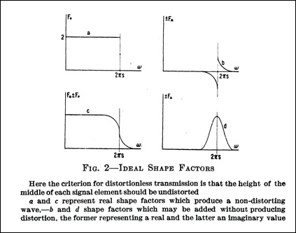
Figure 1 : (from
Nyquist) First Nyquist Condition
In the figure, curve
a
is a transfer
function that meets Nyquist's first criterion. Curve
b
represents a real
function, and curve d represents an imaginary
function (odd and even functions, respectively
around ω =
2πs) that
can be added to curve a to create a new transfer
function, as exemplified by curve c in the figure, which continues
to meet Nyquist's first criterion.
The second of Nyquist's conditions requires the period of
the signaling elements to be constant, regardless of the
actual bit sequence. The figure below (taken from Figure 3
in Nyquist's paper) shows the transfer functions that
satisfy this condition.
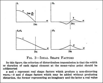
Figure 2 : (from
Nyquist) Second Nyquist
Condition
In this case, curve
b
is an imaginary
term and curve d is a real term which can be
added to curve a.
The third Nyquist criterion requires the area under the
curve of the filtered pulses to be directly related to the
magnitude of the transmitted pulse. This last property is
seldom mentioned in the literature.
The transfer function of a filter that is free of ISI has
to meet both
the conditions that
are shown in Figure 2 and Figure 3 in Nyquist's paper.
Raised
Cosine Filter versus Matched Filter
As mentioned earlier, the
Raised Cosine filter meets the Nyquist Criteria for an
input that consists of rectangular pulses.
In the
absence of adjacent channel interference, the filter that
provides the best SNR in the Additive White Gaussian Noise
(AWGN) channel is not the Raised Cosine filter, but instead
is a Matched Filter. For the rectangular signaling pulse,
the Matched Filter is simply a Finite Impulse Response
(FIR) filter that has a rectangular kernel, with a length
that is the same duration of the input pulse. The Matched
Filter for a rectangular pulse can also be viewed as an
integrate-and-dump detector.
The following figure shows the transfer functions of a
Raised Cosine filter (β = 1) and a Matched Filter for the
same rectangular pulse.
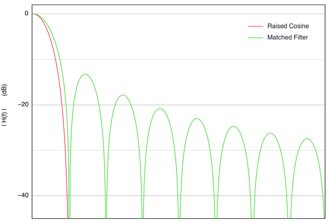
Figure 3 : Transfer
Function for two Nyquist Filters
The next figure shows the
performance difference between these two Nyquist filters
when they are used in an FSK demodulator (5 bit Baudot).
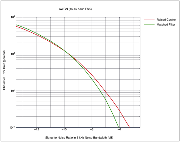
Figure 4 : FSK Error
Rates
As shown above, the Matched
Filter requires almost 0.5 dB less SNR to reach a 1%
character error rate, and about 0.75 dB less SNR to reach a
0.1% error rate. The Matched Filter's main drawback is that
it uses up a much
wider bandwidth,
thus more susceptible to adjacent channel interference.
The next figure shows a Raised Cosine filter that is too
narrow (0.6 times and 0.8 times the proper bandwidth needed
for baud rate) and thus producing intersymbol interference
even when the SNR is good.
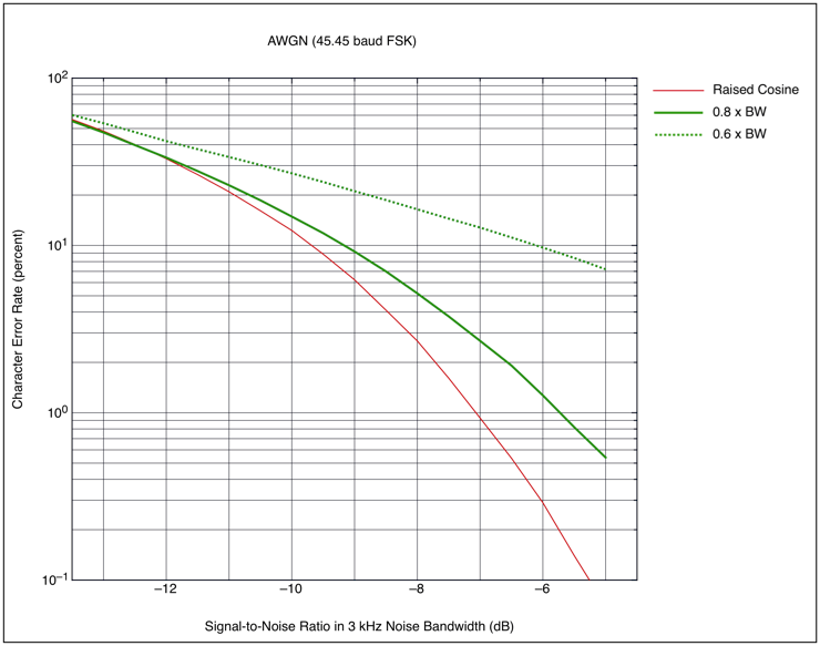
Figure 5 : FSK Error
Rates for Raised Cosine with narrow
Bandwidths
The following figure shows a Raised Cosine filter that is
too wide (1.5 times and 3 times the proper bandwidth needed
for baud rate) and thus including more noise.
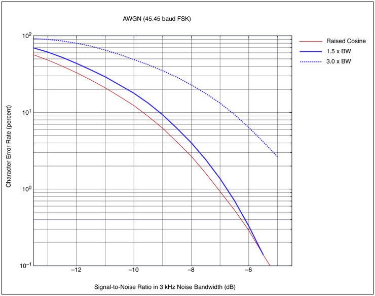
Figure 6 : FSK Error
Rates for Raised Cosine with wide
Bandwidths
Figures 5 and 6 illustrate that one cannot make the Raised
Cosine perform any better by narrowing or widening its
bandwidth.
Extending
Nyquist Filters
Starting with a known Nyquist
filter, we will now show how to obtain a family of filters
which also satisfy the Nyquist criteria.
By starting with a Raised Cosine filter, the algorithm
produces a sequence of a filters that approaches the
Matched Filter in the limit.
Each filter in the sequence has successively wider
bandwidth, but unlike the narrow and wider Raised Cosine
filters mentioned earlier, this set of filters remains
compliant with Nyquist's conditions. This allows one to
choose better bandwidth tradeoffs.
Let us first regress on the Nyquist conditions. Nyquist
filters implicitly guarantees the integrity of data values
that are taken at mid-bit locations, whether the bit
sequence consists of alternating bit, or alternating pairs
of bit where the data remains constant every two bits. This
is shown for a Raised Cosine filter in the following
figure.
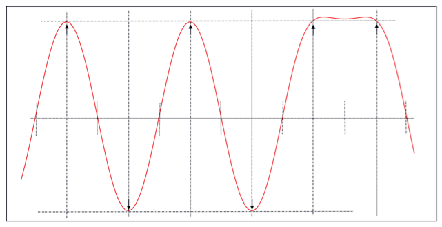
Figure 7 : Raised
Cosine Filter Response
Even though there is some
ripple from the filter's impulse response, notice that the
sampling values for the last two samples are located at the
same levels as the sample amplitudes for the isolated bits
before it. This is Nyquist's first condition. The time
offsets are fixed by Nyquist's second condition.
What this implies is that when a bit stream with bit period
T is passed through a Nyquist Filter that is designed
instead for a bit period of T/2 (i.e., a Nyquist filter
that is exactly twice the bandwidth), the sampling values at
0.25T and 0.75T from the leading edge zero crossings are
correct values.
Since the superposition of
these two samples must also yield the correct sampling
value, we can write the following recursion,
![]() [Equation
1]
[Equation
1]
In Equation 1, if
hN(t) is the impulse response of
a Nyquist filter, then hN+1(t) is an impulse response of a
filter that also satisfy the Nyquist conditions.
By starting from a known Nyquist Filter
h0(t), we can therefore derive a
family of Nyquist filters h1(t),
h2(t), etc. Specifically, there
is a family of Nyquist filters that starts with a Raised
Cosine filter.
In C, this recursion can be written as
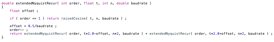
The extendedNyquistRecur()
function returns a standard Raised Cosine kernel when
n=1. The raisedCosine() function can be replaced by
any other Nyquist filter.
Impulse
Response of Extended Raised Cosine
Filters
Starting with the impulse
response h0(t) of a Raised Cosine filter,
Figure 8a shows the impulse responses of successive
applications of Equation 1.
h1(t)
is the second order extension (first recursion) of the
Raised Cosine filter, h2(t) is the third order
extension (second recursion) of the Raised Cosine filter,
etc.
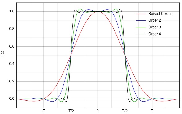
Figure 8a : Impulse
Responses of "Extended Raised Cosine" Filters
The above shows the typical β=1
Raised Cosine for a baud rate of 1/T as having a zero
impulse response at t=T. And, as the filter order
increases, the impulse response appears to converge to a
Matched Filter, which is a rectangle between (-T/2 and
T/2).
Figure 8b shows the same plots in Figure 8a, expanded in
the region of t=T, which is the sampling point of the next
bit.
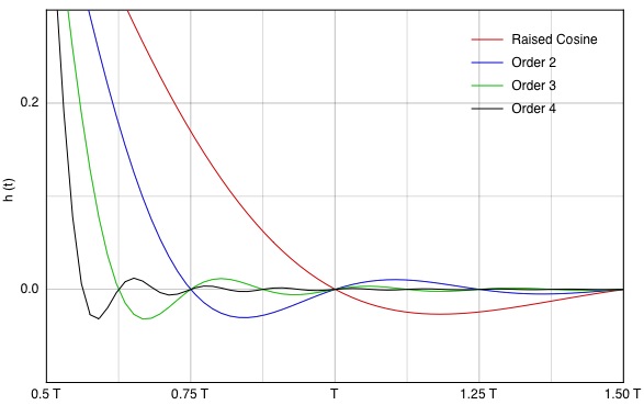
Figure 8b : Impulse
Responses of "Extended Raised Cosine" Filters around
t=T
It
can be seen that for the basic Raised Cosine, ISI increases
very rapidly when the baud rate is higher than the designed
baud rate.
Transfer Function of Extended Raised Cosine Filters
Starting with the Fourier
relationship
![]()
together with the Fourier Scaling theorem and Fourier Shift
theorem,
![]()
and
![]()
the Fourier Transform of Equation 1 becomes
![]() [Equation
2]
[Equation
2]
With the Euler formula, the recursion simplifies to
![]() [Equation
3]
[Equation
3]
The following figure shows the transfer functions from the
first few applications of Equation 3:
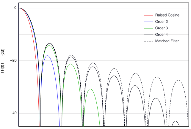
Figure 9 : Transfer
Functions of "Extended Raised Cosine"
Filters
Notice from Figures 8 and 9 that the sequence of extended
Raised Cosine filters approaches the Matched Filter
(rectangular impulse response and sin(x)/x transfer
function).
Equation 3 also looks deceptively simple: a Nyquist filter
results from another Nyquist filter of twice the bandwidth
that is multiplied by a cosinusoidal function. In the next
section, we shall see that this formulation is also very
effective.
Performance
of Extended Raised Cosine Filters
Figure 10 shows the character
error rate when a 2nd order extended Raised Cosine filter
is used in an FSK demodulator, together with character
error curves for the fundamental Raised Cosine filter and
the Matched Filter for comparison. Figure 11 shows the
character error rate for a 3rd order extended Raised Cosine
filter.
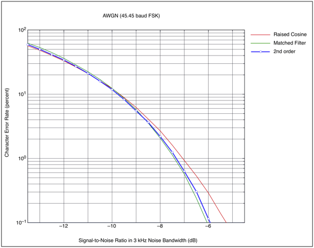
Figure 10 : FSK Error
Rates for 2nd order extended Nyquist
Filter
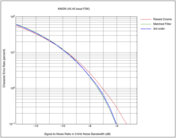
Figure 11 : FSK Error
Rates for 3rd order extended Nyquist
Filter
Notice that for practical
purposes, the filter shown the Figure 10 is virtually equal
to the performance of a Matched Filter. The third order
filter in Figure 11 shows a very small improvement at the
expense of a wider -30 dB bandwidth.
Frequency Domain Design
Notice
from Figure 8 that the impulse response for all the filters
have the same -6 dB width. However, the impulse responses
do not all cross the y axis at 0
Conclusion
Starting from a known Nyquist filter, we have presented an
effective recursive algorithm (Equation 1) to create a
family of filters that satisfy the Nyquist criteria. For a
Raised Cosine filter, the sequence of these "extended
Nyquist filters" appear to converge to a Matched Filter,
i.e., the impulse response of a filter in the sequence
approaches a rectangle and the transfer function approaches
a sin(x)/x function.
We further showed that even the first iteration of the
algorithm, which has a much narrower bandwidth than the
Matched Filter, comes very close to the performance of a
Matched Filter when used as a data filter for FSK.
Reference
H. Nyquist, "Certain Topics In Telegraph
Transmission Theory," AIEE Transactions, Vol 47, April
1928 pp 617-644.